When installing a network access control system, there are a number of common installation errors, typically a consequence of unplanned work, which can cause problems for your installation, damage your equipment and delay completion. The tips below are an attempt to avoid the most common mistakes installers make and therefore can be useful for both novice and experienced specialists.
About the Key terms for “Earth”: is a minus 12 volts supplied from the power supply to the controller. The terminals are also often referred to as “the GND”, “Ground” and “-12V”.
An RS-485 line has two wires: One wire connects all terminals «A», the other, all terminals «B». Despite its apparent simplicity, not everyone has a full understanding of how to build a line of communication, and there are many pitfalls.
The basic rules for installing RS-485 lines for an ACS are:
1) The performance of a twisted pair cable: Even at small distances it can be difficult to protect the communication line from interference. For best results use a Ethernet UTP/FTP Cat 5 cable. When laying lines outside buildings, it should be understood that not all Ethernet cables are designed to operate in all weather conditions so make your cable choices carefully.
2) Do not lay the communication line next to 220/380 volts power cables, i.e. not closer than 20 centimetres. If there is absolutely nowhere else to run, then provide the cable with an additional protective sheath/shield, and ground it whenever possible. If you have to cross power lines, then only do so at right angles.
3) All devices must be incorporated in turn and in one line. All varieties of “trees” or “fan” type installations are dangerous options. If you are considering a “branch” of 2 meters to the side, it is better to make a loop of 4 meters. Loops though can create problems due to lengthening of the line but much less so than “branches”. It should also be remembered that the converter does not have to be on the end of the line and if it turns out that you have a line length of >1000 meters or more than 40 devices, you should look for solutions to partition into smaller segments and to use additional converters.
4) At the ends of the line you need switched load resistors (120 ohms) for echo cancellation. On many devices, these are already included, you just need to install a «LOAD» jumper to enable them. If this resistor on the device is not present, then it should be added to the package and connected to terminals A and B on the connector. If the converter or the controller is not on the edge of the line, connection of a resistor is not needed.
5) Always combine ground from all controllers as it is vital for the longer lines (over 50 meters) and a larger number of devices (5) on the line. It is necessary for balancing potential differences arising between different power supply controllers. In the case of power controllers from different AC phases and when you have two controllers in the line such connection may be required. Differences of up to 5 volts can be handled locally by the controller but differences of more than 15 volts can lead to connection node failures. Therefore, when laying the line it is recommended to use two twisted pairs, one as the leading link and the other by combining the two wires, connecting the ground, thus ensuring a stable operation of the link. On the converter the ground terminal is designated with the letter «G».
6) The location of the converter in the link is not critical, but still there is a simple rule, the closer to the converter/ controller, the better. The consequence of this rule is the location of the converter in the link center. However, following this rule should not lead to a significant lengthening of the line. The shorter the link, the better the connection.
7) Prior to installation, verify whether the software is able to customize the network address of the controller. If not – configure before installation – this will save on start-up time.
Dallas, TM и iButton
Dallas, TM and iButton ACS synonyms, are also the name of the same interfaces for connecting readers. Also at a distance of 2 meters it is strongly recommended to use a twisted pair, and the distance of more than 30 meters, not to experiment. To connect here you need at least two pairs – one signal itself, twisted with a wire connected to ground, the second a power supply of 12 volts, also twisted with a wire connected to the ground. In general, it is better to connect controllers and readers to Ground with thicker wires. It should also be noted that the 12 volts supplied to the reader shall preferably come through resettable fuse, for example «MF-R050». It is recommended to install this as close as possible to the controller or power supply. It will protect the system from short-circuit.
Wiegand
With Wiegand to connect the reader to the controller two data signals DATA0 and DATA1 are used. It has a longer range – up to 100 meters. The most frequent error is to use a single twisted pair for both signals. Proper switching involves two twisted pairs, one for DATA0 / Ground, second DATA1 / Ground. Rule – “the better the grounding/earthing, the better the connection”. It allows you to connect not only a few readers to a single controller, but several controllers can be connected to one reader.
Power supply
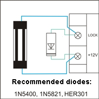
With power installations there can also be errors. For long cable runs of 12 volt power, a significant role is played by resistance and inductance. In the first instance this can quite easily be corrected with a thicker wire, but for the second it is not so obvious, and for power cables of more than 20 meters it is necessary to apply measures to protect against it. This second problem manifests itself as a powerful short-term surge of voltage in the power supply wires when current is switched off to the lock, which in turn releases the lock. So to control such sufficiently you need to put an additional capacitor near the controller, capacity 1000-4700 microfarads and voltage at a half times the power supply voltage. The longer the wire to the lock and more current, the greater the capacitance of the capacitor. For some electricians, it seems natural to install a switch in the power controller circuit, but the electromagnetic lock in this case ,has no way of dumping the energy, if it has no bypass diode (picture). If there are too many wires connected to the minus and plus power supply this can create a problem. For the signal wires, for example, sensors and readers, it is possible to apply a special crimping sleeve. It gives a good contact and facilitates the pushing of the wires in the terminal controller. This requires special tools for crimping and complexity by combining wires of different diameters.
One option which does not have such disadvantages (except maybe the price) is the use of sprung WAGO connectors. These spring clips are equally well clamped. Thick and thin wires do not require special tools. With proper preparation, in many cases, the installation can be carried out without any screwdriver. Two terminals with five contacts allow you to quickly and reliably take the power and ground to all points of the circuit without screws.
Locks
The lock is a large electromagnet, designed for current to one ampere and 3-5 amperes in the case of electromechanical locks. An electromagnetic lock opens only when the current in its coil is completely stopped. To speed up this process controllers series Z-5R has a built in current damping system which makes it possible to stop it in 0.1 seconds instead of 0.5-1 seconds when using the bypass diode. With a large number of openings per minute occurring in the the circuit this may overheat the power switch and the controller could fail. Therefore, if the number of people passing through the door in a minute is more than 10, it is recommended to install a bypass diode, the voltage and current of the diode must not be less than the values specified for the lock.
Buttons, Reed sensors, Controllers
For these to function, they must receive information from sensors. In general, the representation of the sensor is just two pins. For example, relays, reed switches, push buttons. These devices are “hanging in the air”, that is, not connected to any electrical circuits and it is not important where the signal is connected and where is the ground wire. For output transistor optocouplers, including turnstiles and also probes, where the the ground connects and where the signal is, is important.
Connecting with a twisted pair – the signal is fed on one wire pair and the ground the other. Do not use an earth wire for connecting to other devices – readers and more locks. If the distance is less than 2 meters, it is possible to use a common ground wire for the buttons and reeds, but at distances greater than 5 meters it is better not to experiment and to use a twisted-pair cable. When using the resistor method for identifying the sensors it is recommended to use a twisted pair at any distance to the controller, the resistor can be installed on either side, or near the sensor, or by the controller. When installing resistors near the sensor you can use a single twisted pair, if both sensors are connected to one input. For distances greater than 30 meters resistor identification should be understood.